Smart Water Meter
Single Smart Water Meters
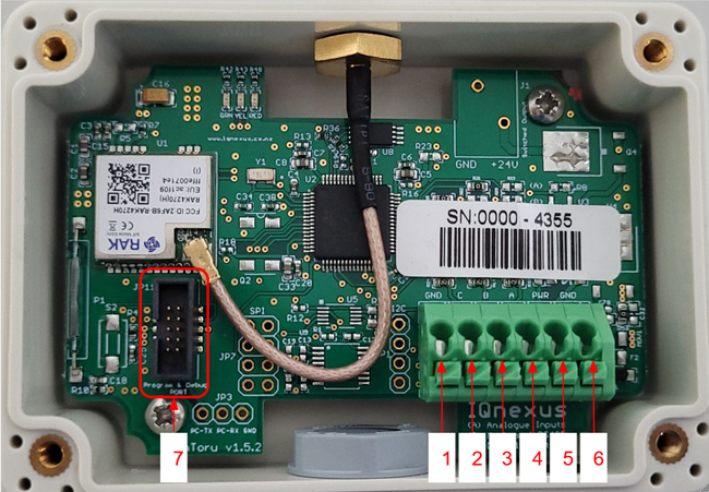
|
GND |
Tamper |
Direction |
Count |
VDD (3V) |
GND |
PC Serial Interface |
Itron
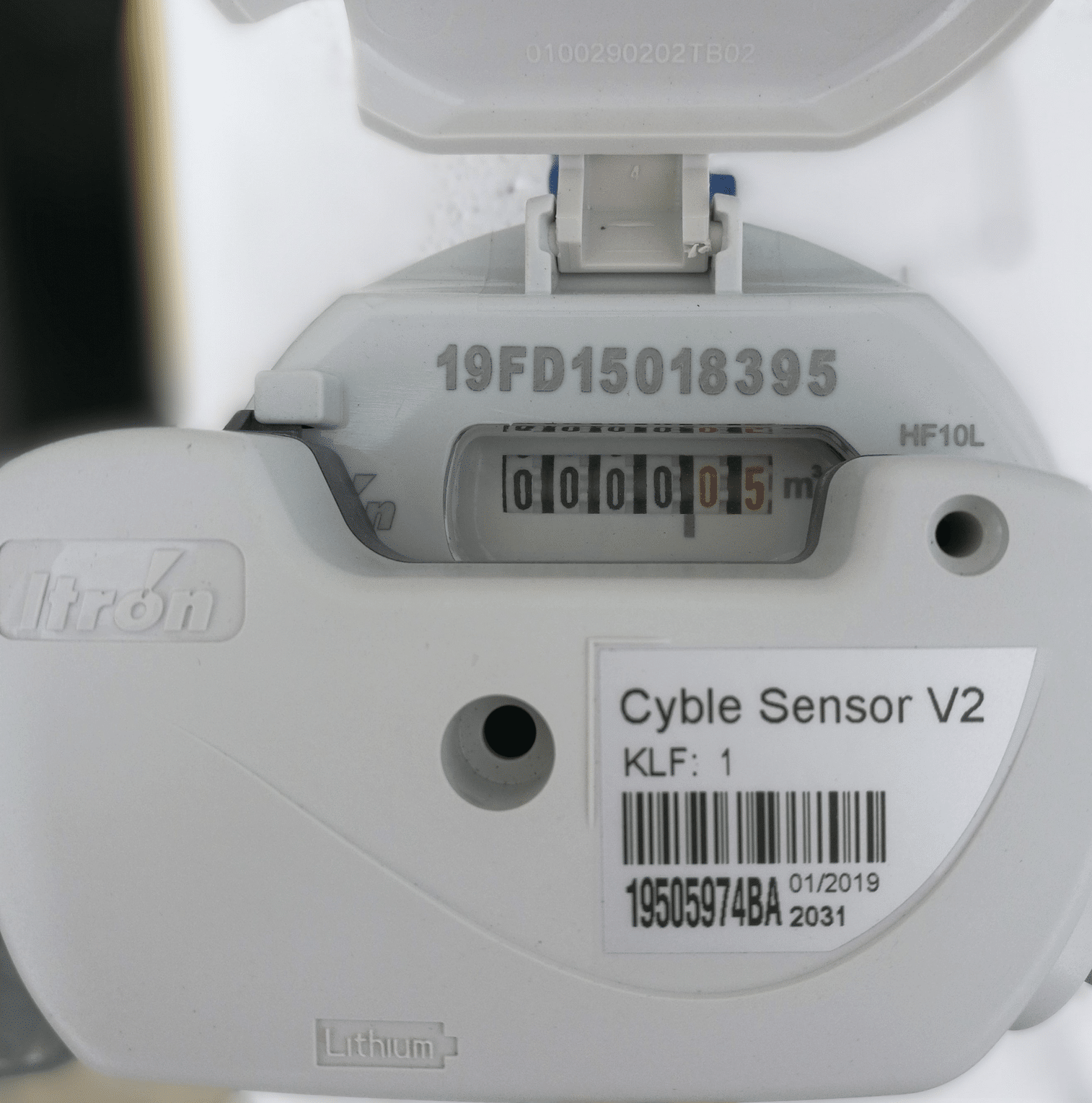
The KLF value lets us know what volume it is reading per pulse. For example, KLF : 1 means 1 m3 per pulse for this meter.
Connection
-
Remove the lid of the box by unscrewing the 4 screws on top
-
Unscrew the cap of the gland and remove the rubber grommet found inside.
-
Pass the cap of the gland through the water meter cable and then pass the rubber grommet afterwards.
-
Pass the cable of the meter through the gland into the inside of the box.
-
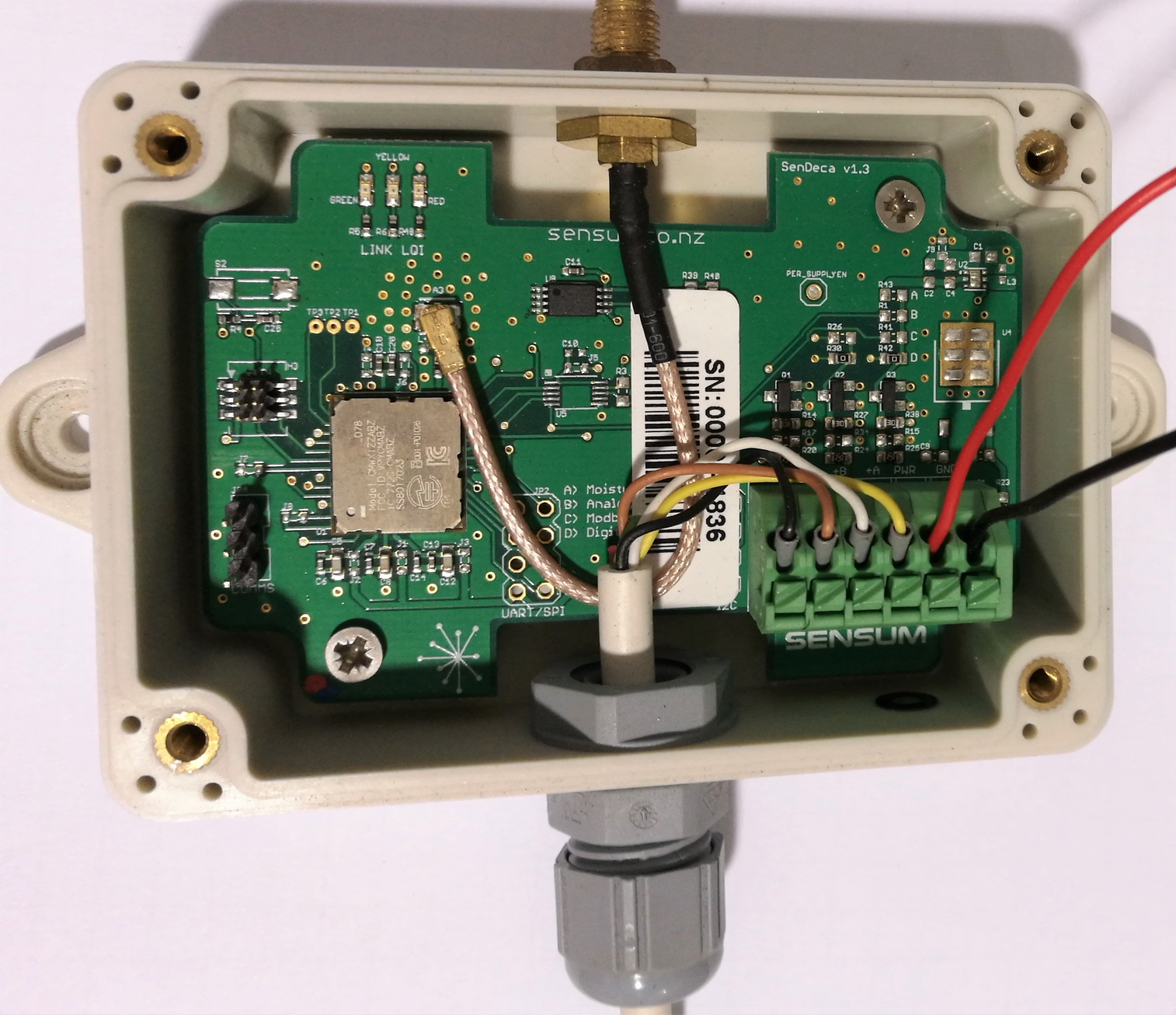
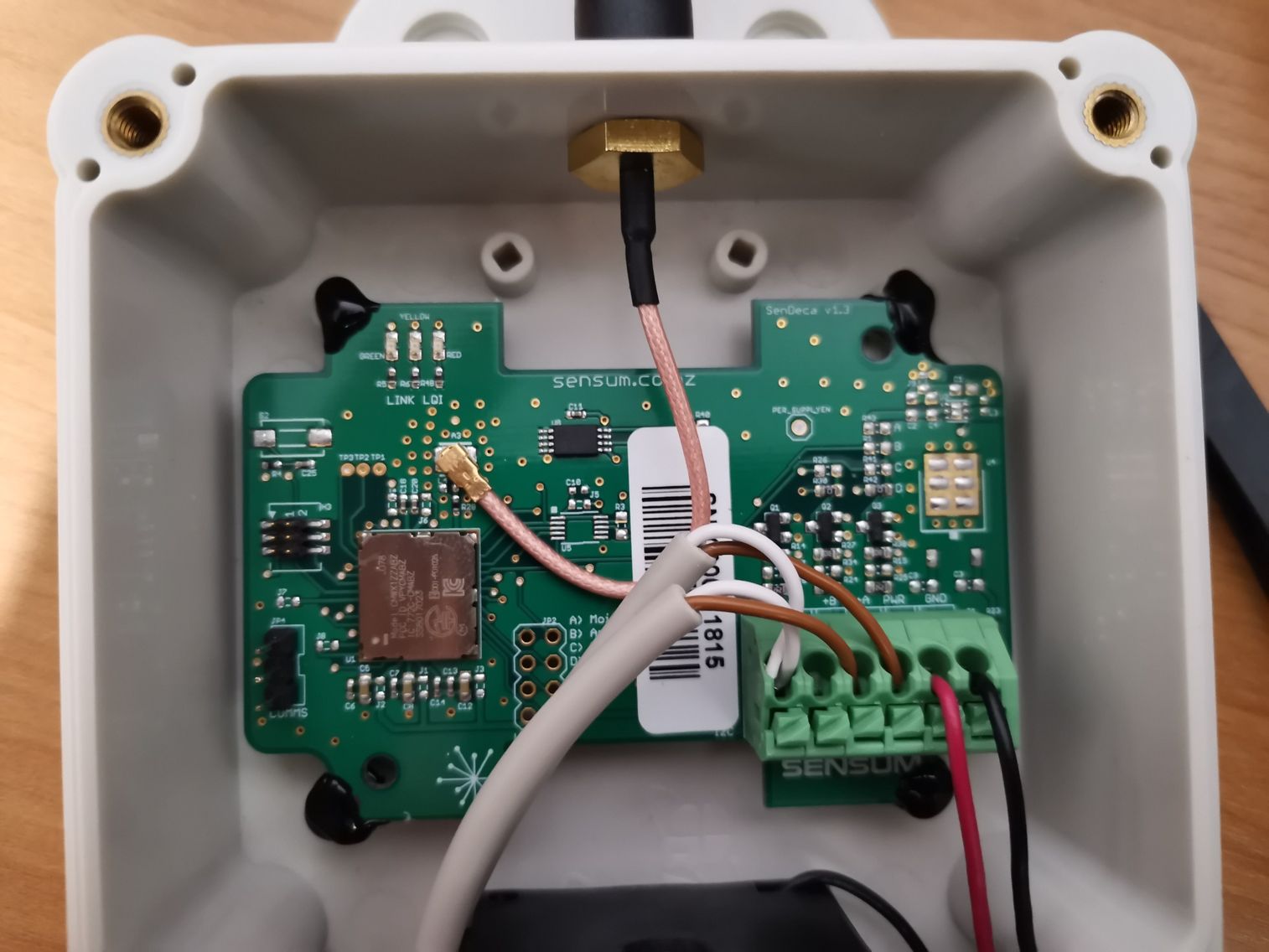
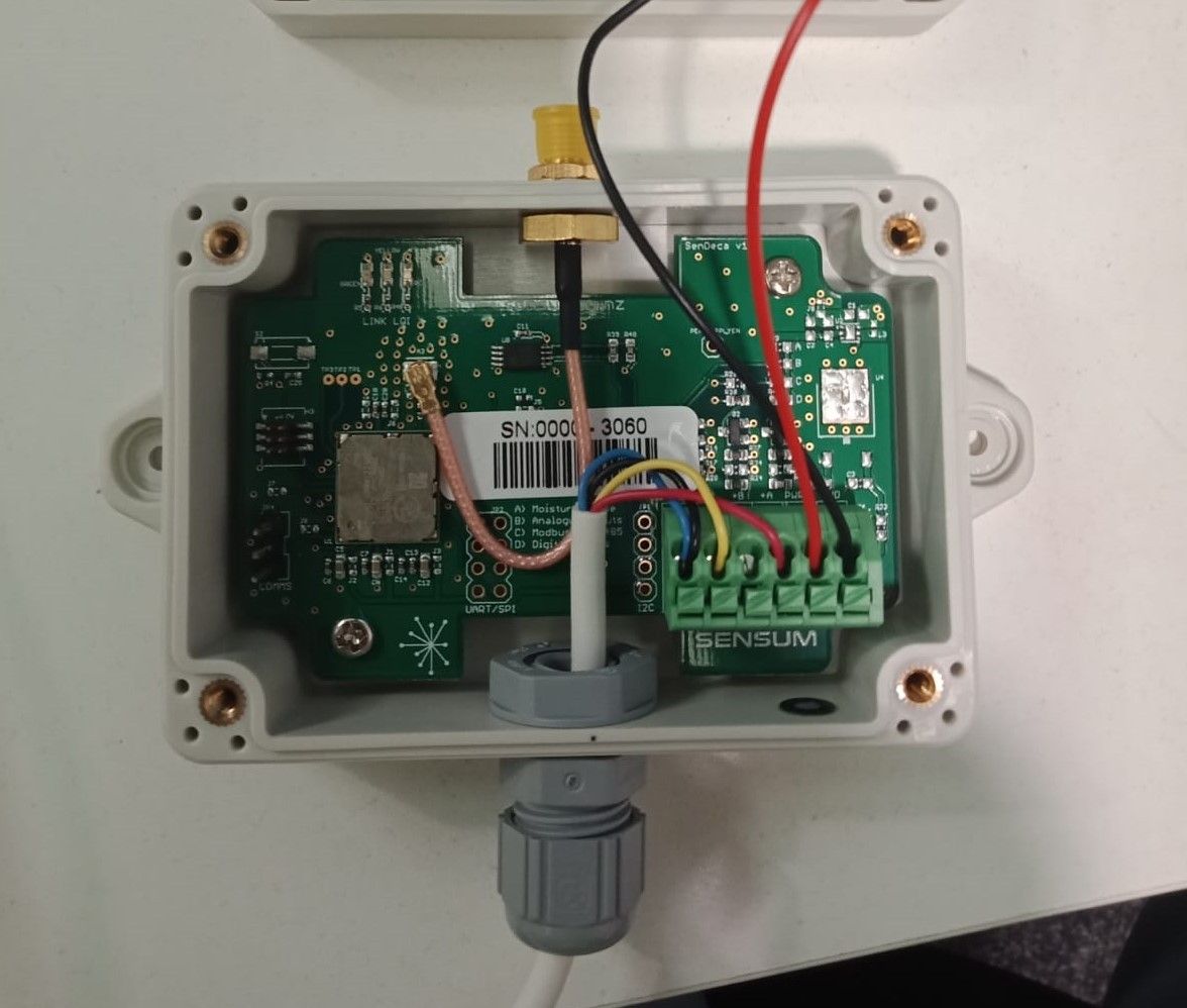
Now that the wires are inside the package they are to be connected to the board through the green connector. Hold down connector buttons to open and release the individual connections. Connect wires according to the figure below.
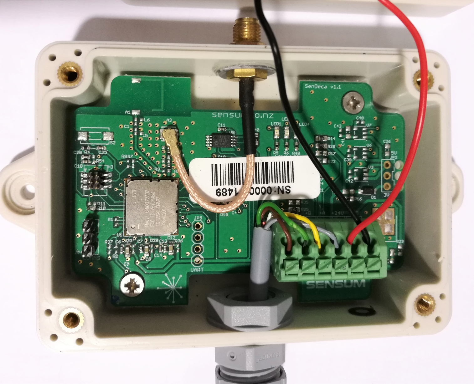
|
GND |
Tamper |
Direction Flag |
Count |
3V |
GND |
-
Count logs each pulse from the water meter.
-
This meter is able to detect forward and reverse flow using the Directional flag.
-
The tamper wire lets you know if the device has been removed or wires cut.
We recommend configuring your device by downlink next.
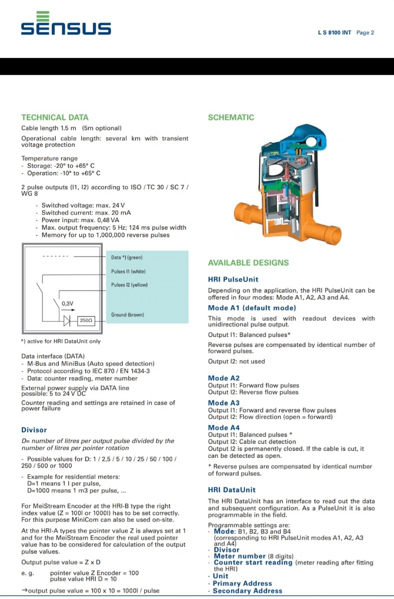
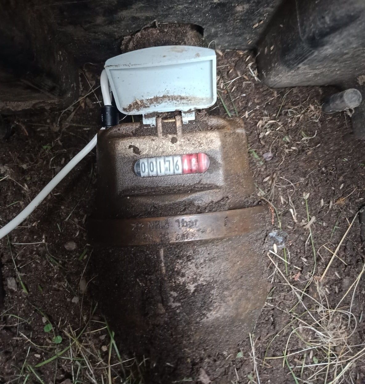
Sensus
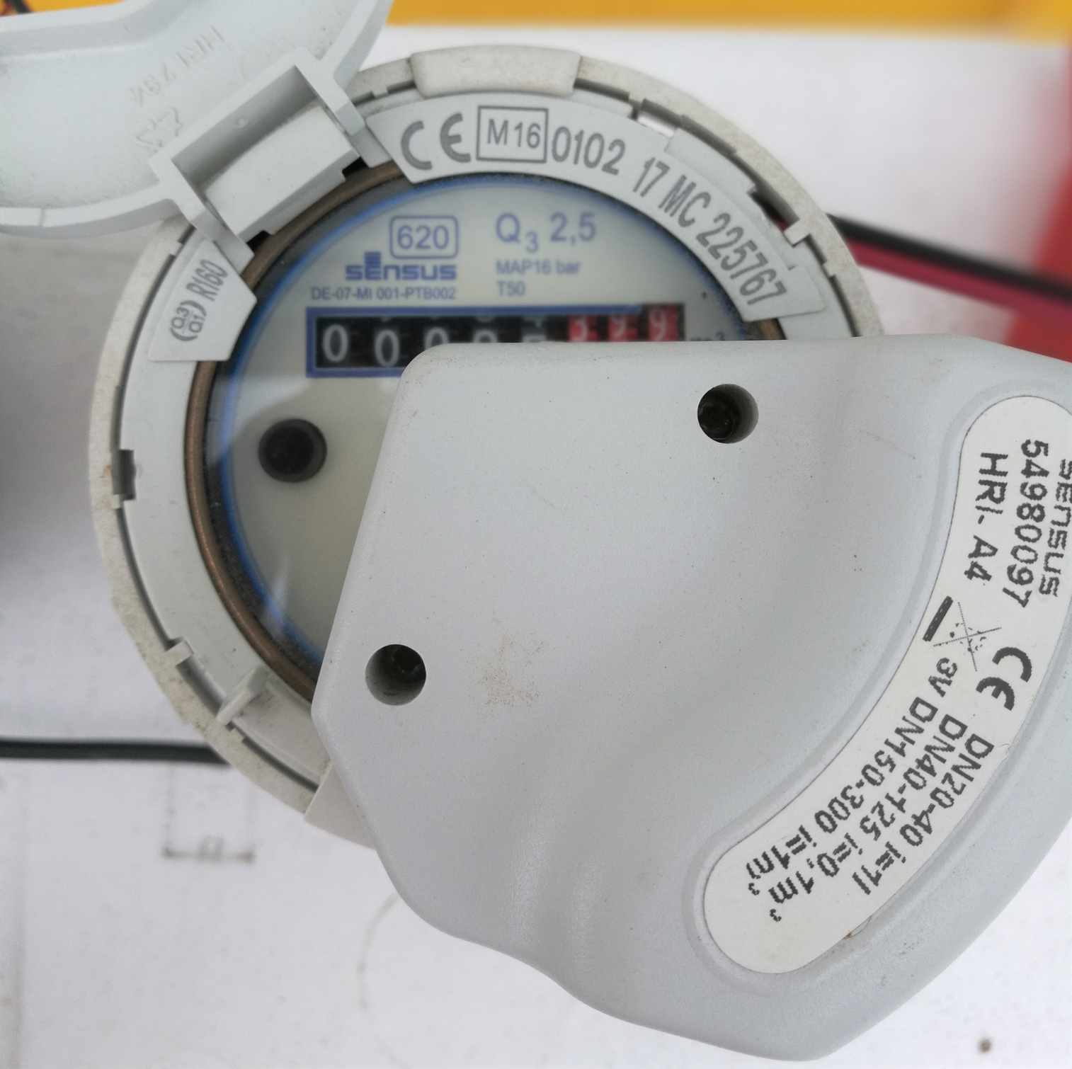
The list of i values based on the water meter model lets us know what volume it is reading per pulse. For example, the DN40-125 model shows i=0.1m3 , this means one pulse corresponds to 100 liters.
Connection
-
Remove the lid of the box by unscrewing the 4 screws on top
-
Unscrew the cap of the gland and remove the rubber grommet found inside.
-
Pass the cap of the gland through the water meter cable and then pass the rubber grommet afterwards.
-
Pass the cable of the meter through the gland into the inside of the box.
-
Now that the wires are inside the package they are to be connected to the board through the green connector. Hold down connector buttons to open and release the individual connections. Connect wires according to the figure below.
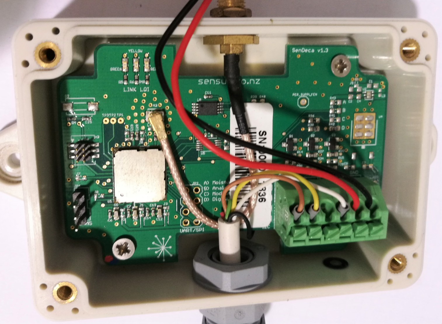
|
GND |
Count |
Tamper |
3V |
GND |
-
Count logs each compensated pulse from the water meter.
-
This meter uses compensated pulses rather than a direction flag.
Compensated means each reverse pulse is balanced by not counting the next forward pulse. -
The tamper wire lets you know if the device has been removed or wires cut.
We recommend configuring your device by downlink next.
Elster V210
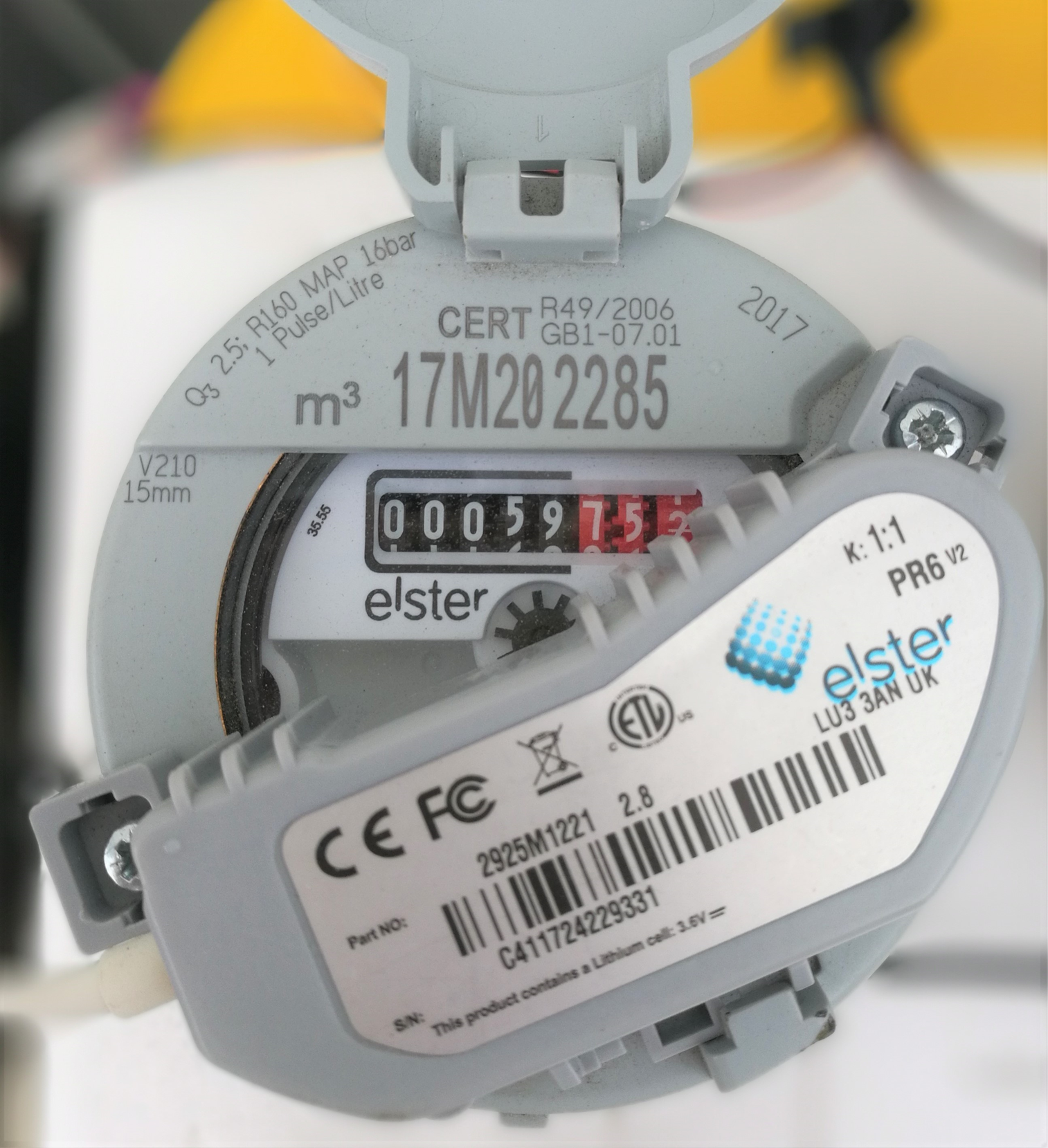
The k: 1:1 at the top right of the device indicates the number of liters per pulse. e.g. 1 liter to 1 pulse.
Connection
-
Remove the lid of the box by unscrewing the 4 screws on top
-
Unscrew the cap of the gland and remove the rubber grommet found inside.
-
Pass the cap of the gland through the water meter cable and then pass the rubber grommet afterwards.
-
Pass the cable of the meter through the gland into the inside of the box.
-
Now that the wires are inside the package they are to be connected to the board through the green connector. Hold down connector buttons to open and release the individual connections. Connect wires according to the figure below.
|
Tamper |
Directional Flag |
Count |
3V |
GND (both) |
-
Count logs each pulse from the water meter
-
This meter is able to detect forward and reverse flow using the Directional flag.
-
The tamper wire lets you know if the battery is low or if the device has been removed or tampered with.

We recommend configuring your device by downlink next.
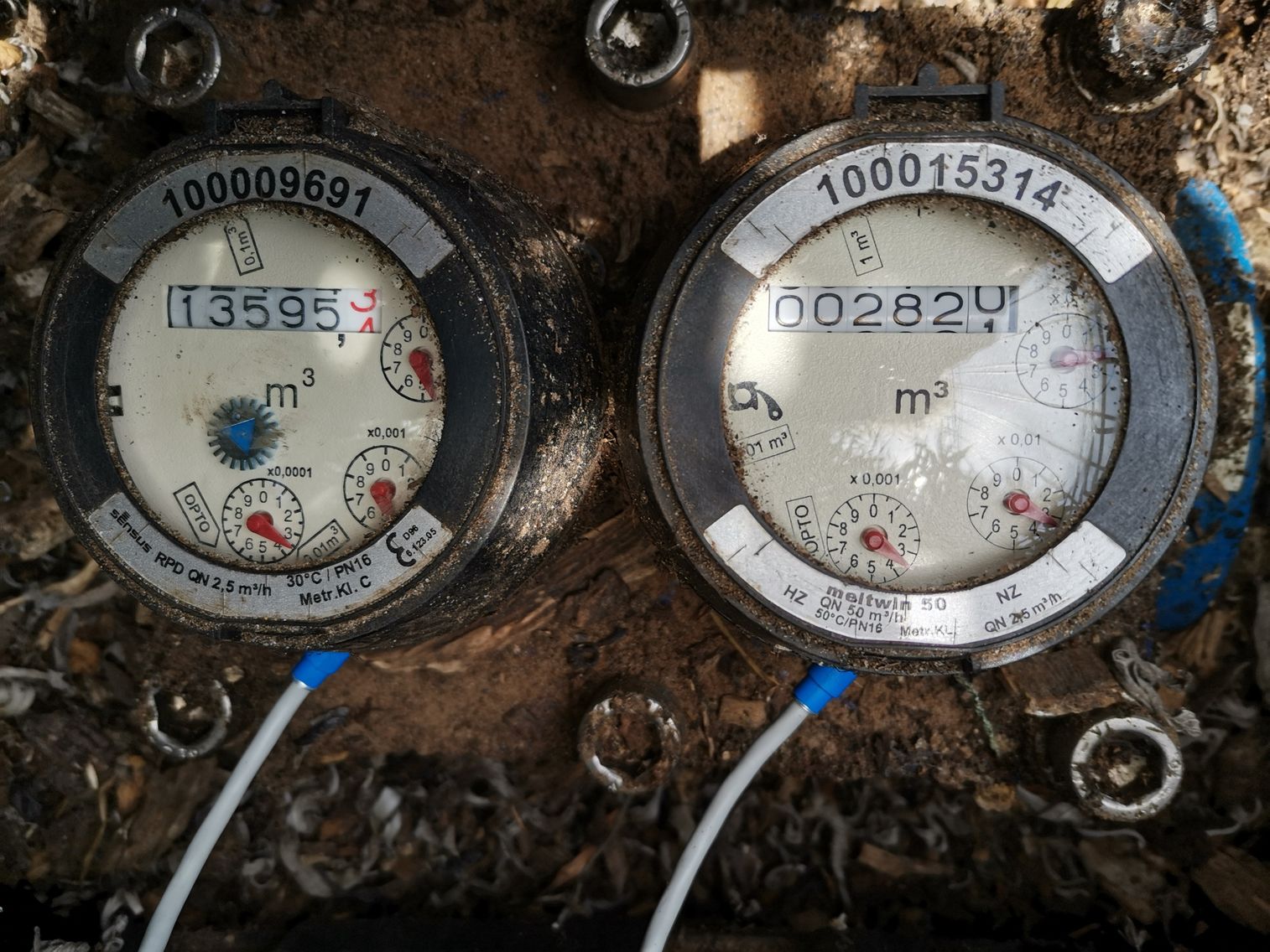
Sensus MeiTwin 50
Some water flow rates vary enough that double water meters are employed, One that is capable of higher precision and one that is for higher flow rates.
Additionally, in some cases it is beneficial to connect two meters to a SenPulse Double rather than use two SenPulse Single devices.
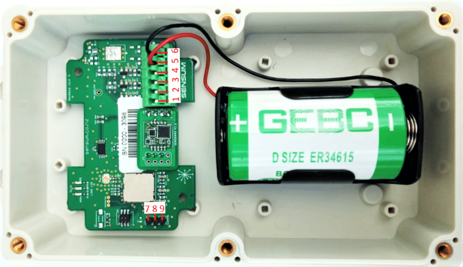
|
GND |
Tamper |
Count 2 |
Count 1 |
VDD (3V) |
GND |
GND |
TXD – to PC |
RXD – from PC |
Sensus meitwin
Connection
-
Remove the lid of the box by unscrewing the 4 screws on top
-
Unscrew the cap of the gland and remove the rubber grommet found inside.
-
Pass the cap of the gland through the water meter cable and then pass the rubber grommet afterwards.
-
Pass the cable of the meter through the gland into the inside of the box.
-
Now that the wires are inside the package they are to be connected to the board through the green connector. Hold down connector buttons to open and release the individual connections. Connect wires according to the figure below.
|
GND (left) |
Tamper |
Count 2 |
Count 1 |
3V |
GND (right) |
-
Count 1 logs each pulse from one of the water meters and Count 2 the other meter.
Elster V100
Connection
-
Remove the lid of the box by unscrewing the 4 screws on top
-
Unscrew the cap of the gland and remove the rubber grommet found inside.
-
Pass the cap of the gland through the water meter cable and then pass the rubber grommet afterwards.
-
Pass the cable of the meter through the gland into the inside of the box.
-
Now that the wires are inside the package they are to be connected to the board through the green connector. Hold down connector buttons to open and release the individual connections. Connect wires according to the figure below.
|
GND (Left) |
Tamper |
Direction |
Count 1 |
3.3V |
GND (Right) |